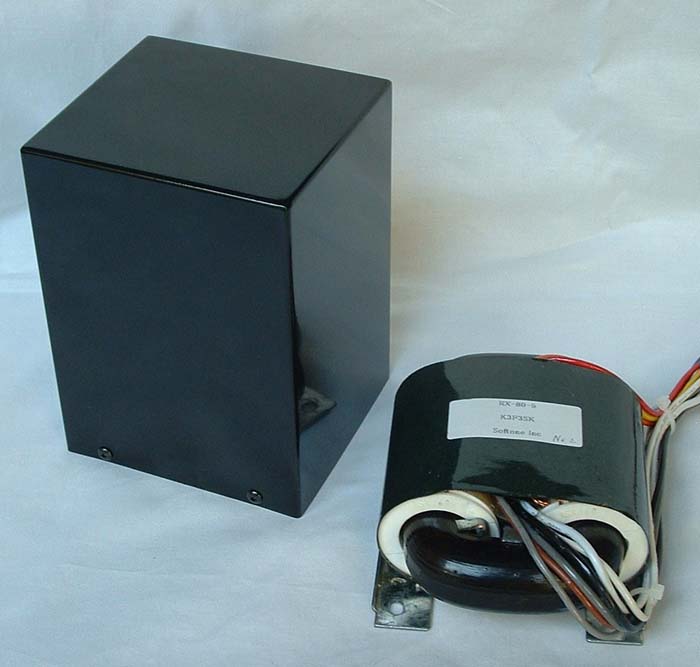
The right on the photo is the R core output transformer in bare condition. The product is enclosed in the square case on the left.
The right on the photo is the R core output transformer in bare condition.
The product is enclosed in the square case on the left.
RW-40-5 is R core audio output transformer for single ended type amplifier. Excellent magnetic properties of R core as well as precisely wound construction of the coil by the computerized manufacturing system achieve the wide bandwidth, low distortion, and low magnetic loss of the transformer.
| Type | Single-Ended |
| Output capacity | 40W at 35Hz |
| Primary impedance | 3,000 ohms, 5,000 ohms, with UL tap |
| Secondary impedance | 4 and 8 ohms |
| 3rd. | cathode feedback winding 16 ohms X 2 |
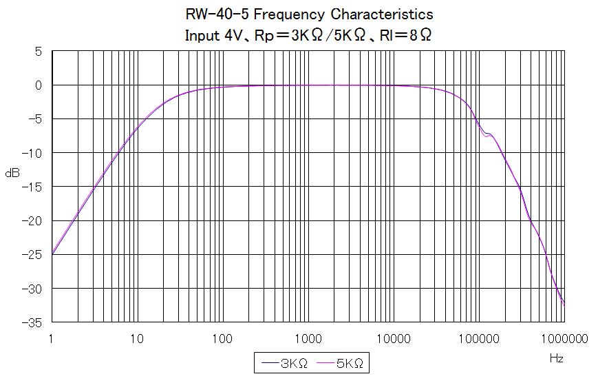
| Frequency bandwidth | 25Hz to 63Khz (-2dB), input=4V, signal source impedance=3,000 ohms 25Hz to 60Khz (-2dB), input=4V, signal source impedance=5,000 ohms |
| Primary inductance (H) |
12H(min.), 15H(max.) (3,000 ohms, DC current 80mA) |
| Primary permissible DC current | 140mA(3,000 ohms), 120mA(5,000 ohms) |
| Recommended primary DC current | 110mA or less (3,000 ohms), 90mA or less (5,000 ohms) |
| Power loss | 0.23dB 8ohms |
| DC resistance | Primary B to 9.5K : 168ohms Secondary 0 to 8 ohms : 0.17ohms 3rd. 0 to 16 ohms : 4.18 ohms |
| Dielectric withstanding voltage between primary, secondary and 3rd. . | 2KV AC |
| Maximum permissible voltage of primary B to 9.5K | 1KV AC |
| Core | Type R160 160W core |
| Shape | Enclosed in square case, the same mounting dimensions as those of Tango XE60,FC-30 |
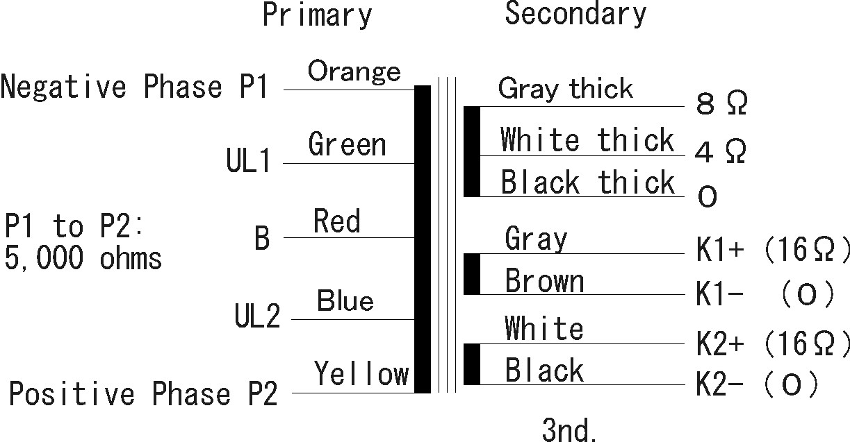
| Connections | Lead wires |
| Overall dimensions and weight | W: 110mm, D: 100mm, H: 150mm, Wt.: 3Kg W: 4.33inch, D: 3.94inch, H: 5.91inch, Wt.: 6.6lbs. |
| Case color | black, silver |
| Price | US$220 (excluding tax and shipping) |
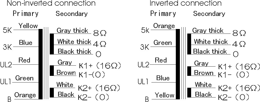
The table below describes the selection of load impedance and the relation of the phase between the primary and secondary and 3rd. You can select non-inverted connection between the primary and secondary and 3rd for two-stage amplifier and inverted connection for three-stage amplifier. When the load is selected to 5,000 ohms, two taps for UL are available; its feedback factor is 50% or 25%. The higher factor makes the plate resistance and distortion lower, however, the sensibility and output power will be reduced.
|
Connected to |
Non-inverted 5,000 ohms |
Non-inverted 3,000 ohms |
Inverted 5,000 ohms |
Inverted 3,000 ohms |
|
Plate |
Yellow |
Blue |
Orange |
Green |
| Screen grid (UL tap factor) |
Red(50%) Green (25%) |
Green (33%) |
Red (50%) Blue (25%) |
Blue (33%) |
|
Power source |
Orange |
Orange |
Yellow |
Yellow |
When
using the cathode feedback winding, the connection of primary winding and cathode
feedback winding is as follows.
There are two cathode feedback windings in RW-40-5. The cathode feedback ratio can be
selected by two windings being used in parallel or in series.
The cathode feedback ratio decreases if it uses in parallel. The cathode
feedback ratio increases if it uses in series.
In addition, a different wire connection adjusts to RW-40-5 by the Non-inverted
or the Inverted. The table below shows the connection of each situation.
| Non-inverted | Inverted | |
|
cathode feedback winding Low |
 |
 |
| Non-inverted | Inverted | |
|
cathode feedback winding High |
 |
 |
Calculating the closed-loop gain and feedback ratio
It explains here as 5K Primary and in parallel cathode feedback winding.
The gain and ratio for 3K Primary and in series
cathode feedback winding is described in the last table.
The
load of the output tube is both the primary winding and cathode feedback
winding in the cathode feedback circuit.
The load impedance of the output tube is not 5K ohms.
The load impedance is as follows.
Rl = ( SQRT(5000) + SQRT(16) ) **2 = 5582 ohms
SQRT : Square route operation
** : Factorial operation
The open-loop gain on the primary side before feedback
Aopen = gm * ( 5582 // Rp )
gm : Transconductance of the output tube
Rp : Plate resistance of the output tube
// : Parallel value operation
The feedback factor β is a voltage ratio (a winding ratio) of load Rl and the
cathode winding .
β = SQRT ( 16 / 5582 ) = 0.054
The closed loop gain on the primary side after feedback
Aclosed = Aopen / ( 1 + Aopen * β )
Feedback ratio = 20 * log( Aopen /
Aclosed ) dB
Example
Value that uses EL34 for output tube
gm of EL34 = 11000uS
Rp of EL34 = 15000 ohms
The open-loop gain on the primary side before feed back
Aopen = gm * ( 5582 // Rp )
= 11000 * 10**-6 ( 5582 // 15000 )
= 11000 * 10**-6 * 4068
= 11 * 4.068 = 44.75
The closed loop gain on the primary side after feedback
Aclosed =
Aopen / ( 1 + Aopen * β )
= 44.75 / ( 1 + 44.75 * 0.054 )
= 44.75 / 3.42 = 13.08
The feedback ratio
Feedback ratio = 20 * log( Aopen / Aclosed ) dB
= 20 * log( 44.75 / 13.08 ) = 10.68 dB
|
Primary 5K |
Primary 5K |
Primary 3K |
Primary 3K |
|
Impedance of cathode feedback winding |
16 |
64 |
16 |
64 |
|
load ImpedanceRl |
5582 |
6195 |
3454 |
3940 |
|
Feedback factor β |
0.054 |
0.101 |
0.068 |
0.127 |
|
Open-loop gain by EL34 |
44.75 |
48.22 |
30.8 |
34.32 |
|
Closed loop gain by EL34 |
13.08 |
8.21 |
9.97 |
6.4 |
|
Feedback ratioBy EL34 |
3.42 |
5.87 |
3.09 |
5.36 |
1. Frequency Characteristics
2. Frequency Characteristic: with different signal source impedances
The frequency characteristic of the audio output transformer varies with the signal source impedance that drives the transformer.
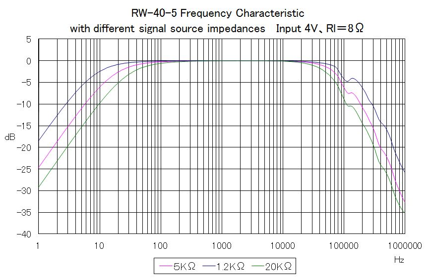
Frequency bandwidth by signal source impedance
| Signal source impedance | Bandwidth |
| 5K ohms (Standard) | 25Hz to 60KHz -2dB |
| 1.2K ohms (Triode tubes) | 11Hz to 80KHz -2dB |
| 20K ohms (beam tubes) | 42Hz to 44KHz -2dB |
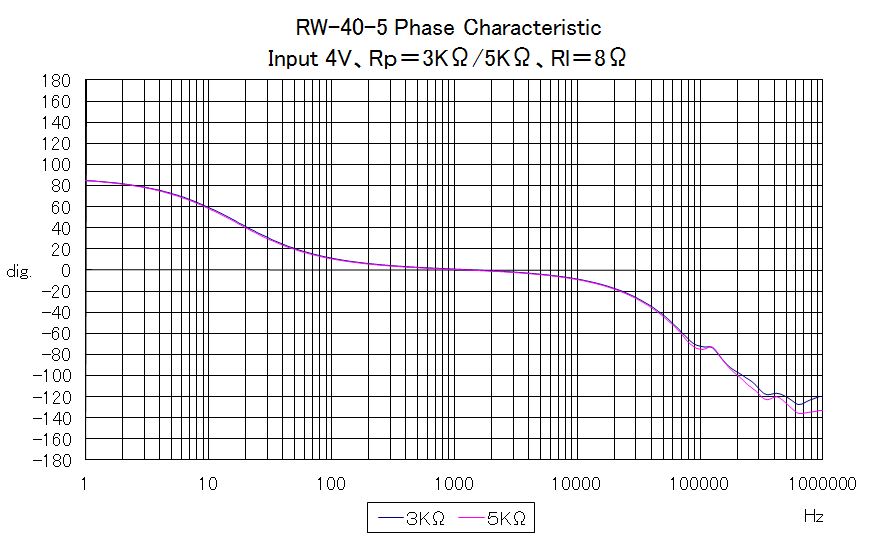
3. Phase Characteristic
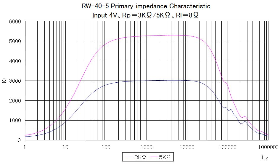
4. Primary impedance Characteristic
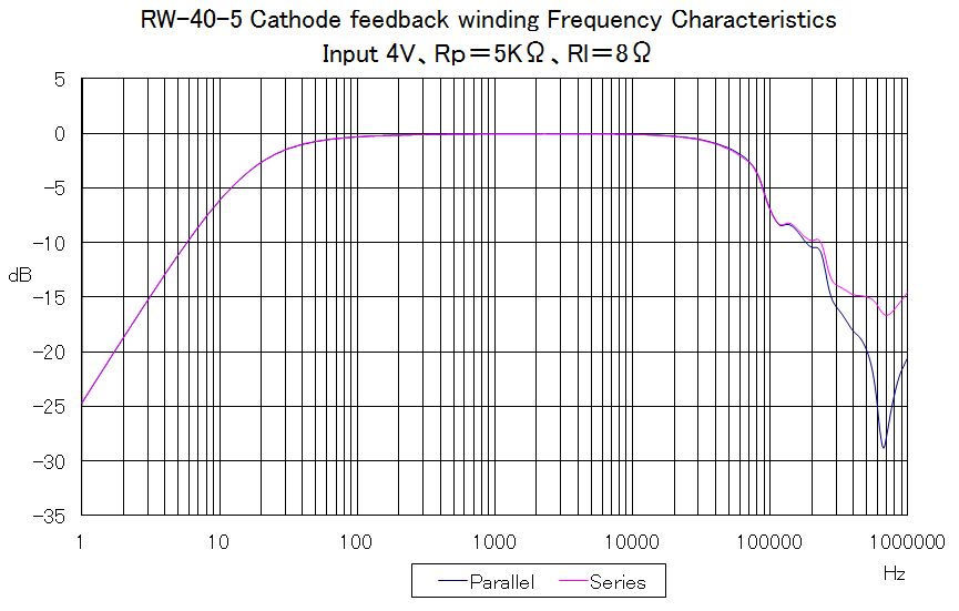
5. Cathode feedback winding Frequency Characteristics
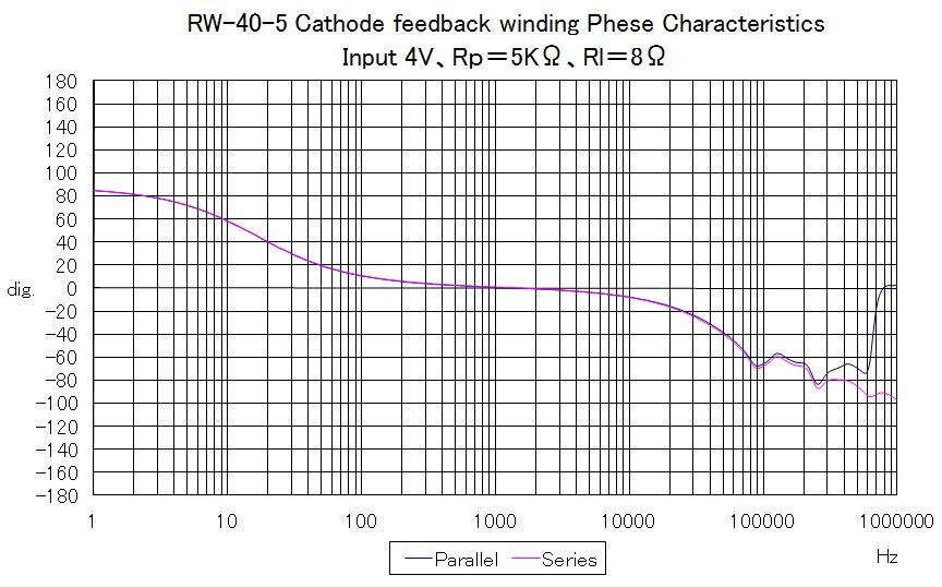
6. Cathode feedback winding Phase Characteristic
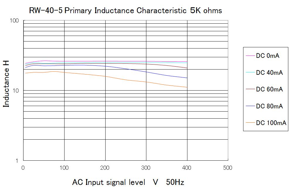
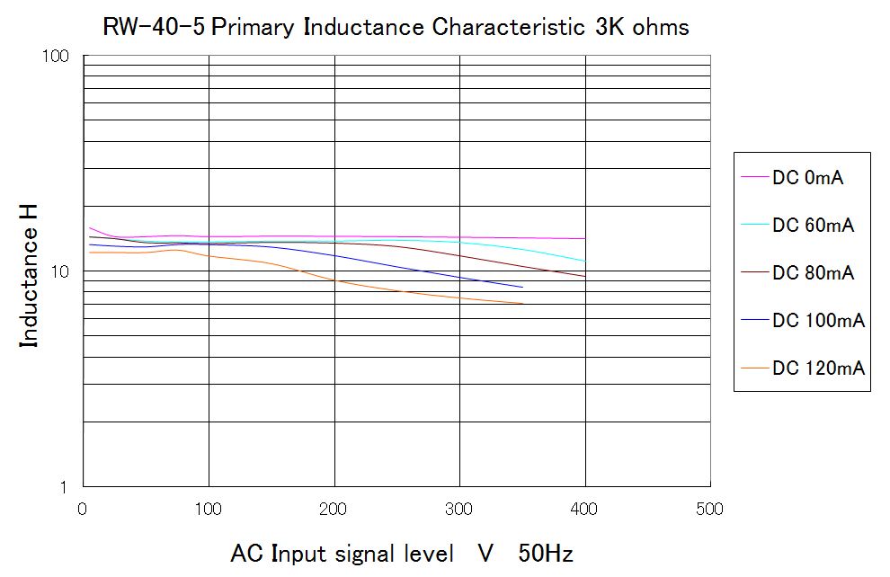
7. Primary Inductance Characteristic
The primary inductance of the single-ended output transformer has a characteristic of constant inductance. With this, the output transformer can drive steadily the loudspeaker without being influenced by the level difference of the superimposed DC current or AC input signal. The less the inductance fluctuates under various conditions, the more solid and stable sound quality can be obtained.
Primary inductance
|
Primary |
Minimuminductance |
Maximuminductance |
DC current |
|
3K ohms |
12H |
15H |
80mA |
|
5K ohms |
19H |
23H |
80mA |
The primary coil of RW-40-5 is perfectly symmetrical the center of which is set at red lead wire. This construction enables RW-40-5 to be used as constant inductance type push-pull output transformer, fairly suitable to build a DC unbalance current proof, maintenance-free type push-pull amplifier. The table below describes the connections and specifications as constant inductance type push-pull output transformer.
| Type | Constant inductance type Push-Pull |
| Output capacity | 80W at 50Hz |
| Primary impedance | 5,000 ohms, with UL (50%) taps |
| Secondary impedance | 4 and 8 ohms |
| 3rd. | cathode feedback winding 16 ohms X 2 |
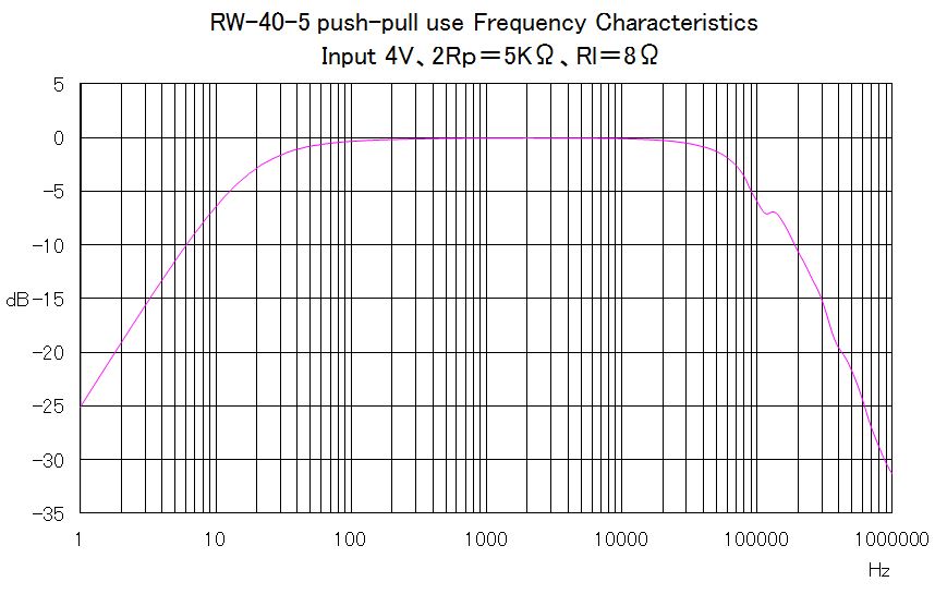
| Frequency bandwidth | 40Hz to 47KHz (-1dB), input=4V, signal source impedance=5,000 ohms |
| Primary inductance (H) | 19H(min.), 23H(max.) |
| Primary permissible DC current | 280mA (for 2 tubes) |
| Primary permissible unbalance DC current | 120mA (recommended within 90mA ) |
| Power loss | 0.23dB 8ohms |
| Dielectric withstanding voltage between primary and secondary | 2KV AC |
| Maximum permissible voltage of primary P-P | 1KV AC |
| Core | Type R160 160W core |
| Shape | Enclosed in square case, the same mounting dimensions as those of Tango XE60,FC-30 |
| Connections | Lead wires |
1.Cathode feedback winding of push-pull use
When using the cathode feed back winding, the connection of primary winding
and cathode feedback winding is as follows. In the case of self-bias, a
self-bias resistance and a bypass capacitor are connected between K1-Brown
and a ground and between K2+ white and a ground.
Calculating the closed-loop gain and feedback ratio
The load of the output tube is both the primary winding and cathode feedback winding in the cathode feedback circuit.
The load impedance of the output tube is not 1.25K ohms of a usual pp circuit
(1/4 of 5K ohms).
The load impedance is as follows.
Rl = ( SQRT(1250) + SQRT(16) ) **2 = 1548 ohms
SQRT : Square route operation
** : Factorial operation
The open-loop gain on the primary side before feedback
Aopen = gm * ( 1548 // Rp )
gm : Transconductance of the output tube
Rp : Plate resistance of the output tube
// : Parallel value operation
The feedback factor β is a voltage ratio (a winding ratio) of load Rl
and the cathode winding .
β = SQRT ( 16 / 1548 ) = 0.102
The closed loop gain on the primary side after feedback
Aclosed = Aopen / ( 1 + Aopen * β )
Feedback ratio = 20 * log( Aopen / Aclosed ) dB
Example
Value that uses EL34(6CA7) for output tube
gm of EL34 = 11000uS
Rp of EL34 = 15000 ohms
The open-loop gain on the primary side before feedback
Aopen = gm * ( 1548 // Rp )
= 11000 * 10**-6 ( 1548 // 15000 )
= 11000 * 10**-6 * 1403
= 11 * 1.403 = 15.43
The closed loop gain on the primary side after feedback
Aclosed = Aopen / ( 1 + Aopen * β )
= 15.43 / ( 1 + 15.43 * 0.102 )
= 15.43 / 2.57 = 6.07
The feedback ratio
Feedback ratio = 20 * log( Aopen / Aclosed ) dB
= 20 * log( 15.43 / 6.07 ) = 8.2 dB
2. Frequency Characteristic of push-pull use
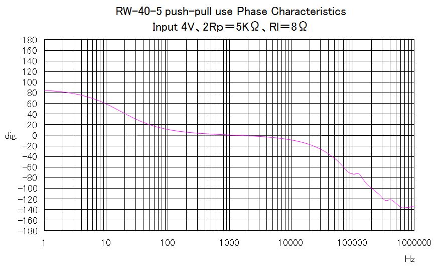
3. Phase Characteristic of push-pull use
4. Other Characteristics
The impedance and inductance characteristics are the same as those of the
single-ended connections. Please refer to those characteristics.