RC-20
Multipurpose Audio Interstage Transformer
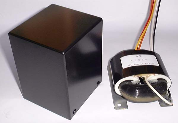
The right on the photo is the R core audio interstage transformer in bare condition. The product is enclosed in the square case on the left.
RC-20 is an R core audio interstage transformer. The excellent magnetic properties of R core and precisely wound coil by the computerized manufacturing system achieve a wide bandwidth, low distortion, and low magnetic loss of the transformer.
Outline
- Wide bandwidth, low distortion, low magnetic loss
- Primary 1+1: Secondary 1.8+1.8
- Advanced versatility supporting various circuits and impedances by selecting series or parallel connection of primary and secondary lead wires.
- Can be used as input transformer for inverted interstage transformer coupling amplifier
- High power handling capacity assured by large-size R core can drive powerfully the power tube by using as driver tube a small or medium power tube such as 6CK4, 6BX7, 12BH7, 6V6T (triode connection), 6BM8T, etc.
- Drive impedance 3.5 Kohms when the primary windings are connected in series.
- DC current can be superimposed in the primary. Maximum permissible current: 30mA when the primary windings are connected in series.
- The secondary can be opened (without load). No peculiar peaks and dips are observed in the frequency characteristics even when the secondary is opened.
- Enclosed in a handy and beautiful square case. The same mounting dimensions as SOFTONE RW-20, RX-40-5 output transformers, and Tango NC-20F.
Specifications
|
Type |
Interstage transformer |
|
Winding configuration |
Primary 1 + 1 : Secondary 1.8 + 1.8 |
|
Primary drive impedance |
Primary two windings in series connection: Standard 3.5Kohms, supporting
from 1Kohms to 5Kohms |
|
Secondary impedance |
Secondary
two windings in series connection: Standard 10Kohms, supporting open (without
load) operation |
|
Frequency bandwidth |
Primary & secondary in series connection: 10Hz to 32KHz (-2db) driven by 4V 3.5Kohms |
|
Primary inductance (H) |
Primary two windings in series connection: 30H at 5V, 50Hz |
|
Primary maximum current |
50mA(AC) |
|
Primary maximum permissible DC current |
30mA |
|
Recommended primary DC current |
20mA or below |
|
Maximum passing voltage |
Primary two windings in series connection: 200Vrms |
|
Primary DC resistance |
Primary in series: 74ohms, primary in parallel: 19ohms |
|
Secondary DC resistance |
Secondary in series: 146ohms, secondary in parallel: 37ohms |
|
Dielectric withstanding voltage between primary and secondary |
2KVAC |
|
Maximum permissible voltage on primary |
1KVAC |
|
R core type |
Type R50 50W R core |
|
Shape |
Enclosed in square case. |
|
Connections |
Lead wires |
|
Overall dimensions & weight |
W: 83mm, D: 78mm, H: 107mm, 1.5Kg |
|
Price |
US$ 120 (excluding tax & shipping) |
Winding configuration & phases
RC-20 has two windings each on primary and secondary. The table below shows the turn ratio (voltage ratio) of each winding and the phases of lead wires.
|
Winding |
Turn ratio (voltage ratio) |
Positive phase (+) lead wire |
Negative phase (-) lead wire | |
|
Primary |
P1 |
1 |
Brown |
Red |
|
P2 |
1 |
Orange |
Yellow | |
|
Secondary |
S1 |
1.8 |
Green |
Blue |
|
S2 |
1.8 |
Violet |
Gray |
Winding combination and its characteristics
Series and parallel connections of primary and secondary windings support various circuitries.
|
Wiring diagram |
Connection |
Winding configuration |
Drive circuit & impedance |
Output circuit |
Characteristics |
Detailed characteristics |
|
|
Primary |
1:1.8 |
Single-ended 1Kohms to 5Kohms |
Single-ended |
Voltage ratio 1.8 assures sufficient drive voltage. |
|
|
|
Primary series
Secondary |
1:0.9 |
Single-ended 1Kohms to 5Kohms |
Single-ended |
No gain in transformer with voltage ratio 0.9, however, this connection
can drive successfully the power tubes into + grid field. |
|
|
|
Primary |
1:0.9+0.9 |
Single-ended 1Kohms to 5Kohms |
Push-pull |
Inverted phase can be obtained and at the same time, the voltage much the same as the primary can be obtained at the grid of power tube to facilitate to drive the power tube. |
|
|
|
Primary |
1+1:1.8+1.8 |
Push-Pull Between P-P 1Kohms to 5Kohms |
Push-Pull |
Push-pull circuitry both drive and power stage assures very low distortion output. |
|
|
|
Inverted interstage transformer coupling
Primary
Secondary |
1:0.9 |
Single-ended 1Kohms to 2Kohms |
Inverted interstage transformer coupling Single-ended |
Low resistance windings and large size core can drive successfully + grid
transmitter power tubes. |
|
|
|
Primary
Secondary |
1:3.6 |
Single-ended 600ohms to 2Kohms |
Single-ended |
Voltage gain 3.6 can be obtained matching to low output impedance components & circuits, 600ohms line, etc. |
|
|
|
Primary
Secondary |
1:1.8 |
Single-ended 600ohms to 2Kohms |
Single-ended |
Can be used as low impedance and wide bandwidth input transformer. |
Several combinations other than the above are also available.
Suitable drive tubes
Suitable drive tubes for RC-20 are small/medium power triodes having plate
resistance 1Kohms to 5Kohms or small/medium power pentodes in triode connection.
Example) 6AH4, 6BX7, 6CK4, 6S4, 6BM8 triode connection, 6F6 t-connection,
6L6 t- connection, 6V6 t-connection, 12BH7A
Shape & dimensional drawing
- Transformer cover case makes it easy to mount this transformer on the amplifier chassis and brings superior form to the amplifier.
- The same mounting dimensions as those of SOFTONE RW-20, RX-40-5 output transformers and Tango NC-20 makes it easy to mount this transformer on various chassis available in the market.
- The beautiful finished case is four-side welded construction and black metallic painted.
- Mounting and overall dimensions
Application Notes
Detailed characteristics
1.Primary
in series connection, single-ended input & secondary in series, single-ended
output
The two graphs below show the characteristics of the transformer when both
the primary and secondary are in series connection for single-ended input
and output, using RC-20 as input transformer 1:1.8
The features are wide bandwidth 10Hz to 32KHz (-2dB) and plain attenuation
characteristic up to 100KHz without peculiar peaks and dips. When the secondary
is opened (without load), the bandwidth is narrowed but no peculiar peaks
or dips are observed. The frequency above 100KHz rises due to the capacitance
between the primary and secondary that passes the signal.
The impedance characteristic also represents a plain curve without peaks
or dips.
2.Primary in series connection, single-ended input & secondary in parallel, single-ended output
The graphs below represent the characteristics when the primary is in series
connection and the secondary in parallel for single ended input and output
using RC-20 as input transformer 1:0.9.
The features are wide bandwidth 15Hz to 100KHz (-2dB) and plain attenuation
characteristic at high frequency. When the secondary is opened (without
load), the bandwidth is narrowed but no peculiar peaks or dips are observed.
The impedance characteristic also represents a plain curve without peaks
or dips.
3.Primary in series connection, single-ended input & secondary push-pull output
The graphs below represent the characteristics when the primary is in series
connection for single ended input and the secondary in push-pull connection
for push-pull output using RC-20 as input transformer 1:0.9+0.9.
The features are wide bandwidth 15Hz to 32KHz (-2dB) and plain attenuation
characteristic up to 100KHz without peculiar peaks and dips. P-P balance
between positive and negative phases is also remarkably good up to 40KHz.
A small difference is observed at 40KHz and above. The frequency above
100KHz rises due to the capacitance between the primary and secondary that
passes the signal.
The graph below represents the characteristics when the secondary is opened (without load). The bandwidth is narrowed but no peculiar peaks or dips are observed. P-P balance is also kept remarkably good.
4.Primary push-pull input & secondary push-pull output
The graphs below represent the characteristics when the primary and secondary
are in both push-pull connection for push-pull input and output using RC-20
as input transformer 1+1:1.8+1.8
The features are wide bandwidth 12Hz to 50KHz (-2dB) and plain attenuation
characteristic up to 100KHz without peculiar peaks and dips. P-P balance
between positive and negative phases is also remarkably good up to 100KHz.
The frequency above 100KHz rises due to the capacitance between the primary
and secondary that passes the signal.
The graph below represents the characteristics when the secondary is opened (without load). The bandwidth is narrowed but no peaks or dips are observed. P-P balance is also kept remarkably good.
5.Primary in series, single-ended input & secondary in parallel, single-ended output, namely at inverted interstage transformer coupling operation
The graphs below represent the characteristics when the primary is in series
connection for single-ended input and the secondary is in parallel and
inverted connection for single-ended output using RC-20 as input transformer
1:0.9 for inverted interstage transformer coupling operation.
The features are wide bandwidth 8Hz to 60KHz (-2dB). The inverted interstage
transformer coupling operation tends to have peaks and dips because the
inverted electro magnetic transmission and non-inverted transmission generated
by the capacitance between the primary and secondary cancel each other.
For this, a slight (+-1dB) peak and dip is observed between 60KHz and 70KHz.
When the secondary is opened (without load), the bandwidth is narrowed
but the peak and dip do not change for the worse.
The impedance characteristic also represents a plain curve with only slight
peak and dip between 60KHz and 70KHz.
6.Primary in parallel connection, single-ended input & secondary in series, single-ended output
The graph below represents the characteristics when the primary is in parallel
connection and the secondary in series for single-ended input and output
using RC-20 as low impedance input transformer 1:3.6.
The bandwidth is 10Hz to 32KHz (-2dB). The features are plain attenuation
characteristic up to 150KHz without peculiar peaks and dips. When the secondary
is opened (without load), the bandwidth is narrowed but no peculiar peaks
or dips are observed. The frequency above 150KHz rises due to the capacitance
between the primary and secondary that passes the signal.
7.Primary in parallel connection, single-ended input & secondary in parallel, single-ended output
The graphs below represent the characteristics when the primary and secondary
are in parallel connection for single-ended input and output using RC-20
as low impedance input transformer 1:1.8.
The features are very wide bandwidth 8Hz to 100KHz (-2dB) and plain attenuation
characteristic at high frequency. When the secondary is opened (without
load), the bandwidth is narrowed but no peculiar peaks or dips are observed.
The impedance characteristic also represents a plain curve without peaks
or dips.
8. Primary inductance characteristics
The primary inductance of the transformer that can be superimposed with DC current on the primary winding has the constant inductance characteristics. This constant inductance makes it possible to drive the power tube steadily without being affected by the fluctuating AC input voltage. The less the inductance fluctuates under various operating condition, the more solid and stable sound quality can be obtained. The inductance of RC-20 is nearly constant, quite independent from the various levels of input AC voltage.
The primary inductance of RC-20 is 30H without superimposed DC current.
The more superimposed DC current increases, the more the inductance drops
and the low-end bandwidth narrows. Although the service limit of DC current
is 30mA, our recommended operating condition is within 20mA.
The graph below shows the inductance characteristic of RC-20. You will
notice its excellent performance. The inductance remains unchanged quite
independent from the various levels of signal and superimposed DC current
unless the core is saturated at 200V input.