Copyright(C) 2013 Shoichi Yoshimoto
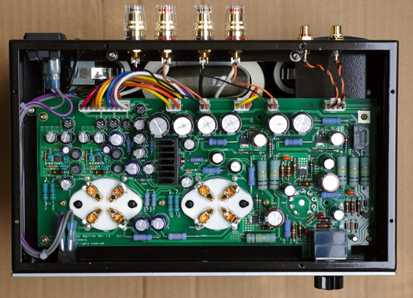
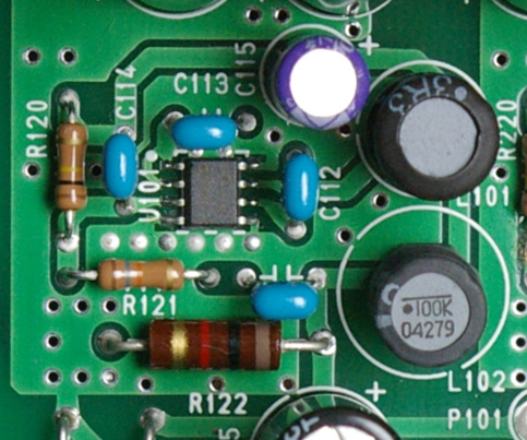
This photograph is only for the explanation. Never open the cabinet because there is a high voltage parts in the inside.
Model8 consists of following parts.
A lot of parts of Model8 are mounted on one print circuit board.
300B is an output tube of a good sound. However, the following fault exists.
To solve these faults, Three stage direct coupled and fixed bias circuit
was developed in Model8.
The following advantage was achieved.
In general, the composition of three stage direct coupled amplifier that
uses 300B is Figure 1.
A high power-supply voltage is necessary to pile the plate voltage of each
stages.
The cathode voltage of 300B becomes a high voltage, and large generation
of heat is caused from the cathode resistor of 300B.
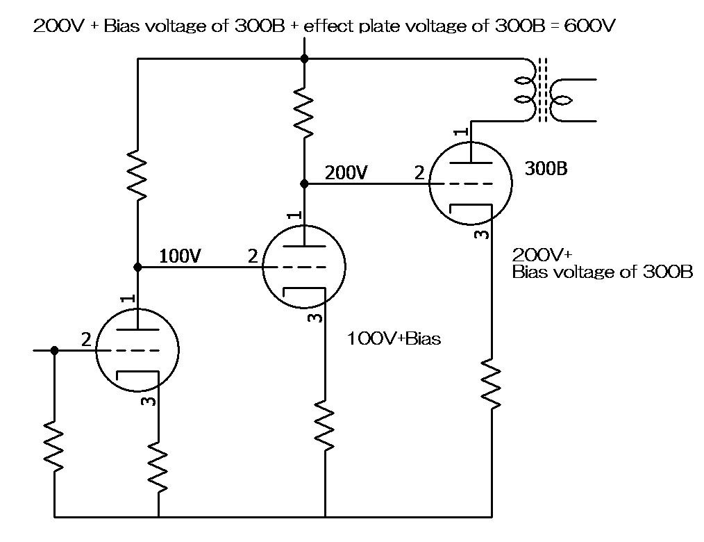
Figure 1
Pch-MOSFET and a minus power supply were introduced in Model8 for operation
by a low power-supply voltage and the deletion of heat from the cathode
resistor.
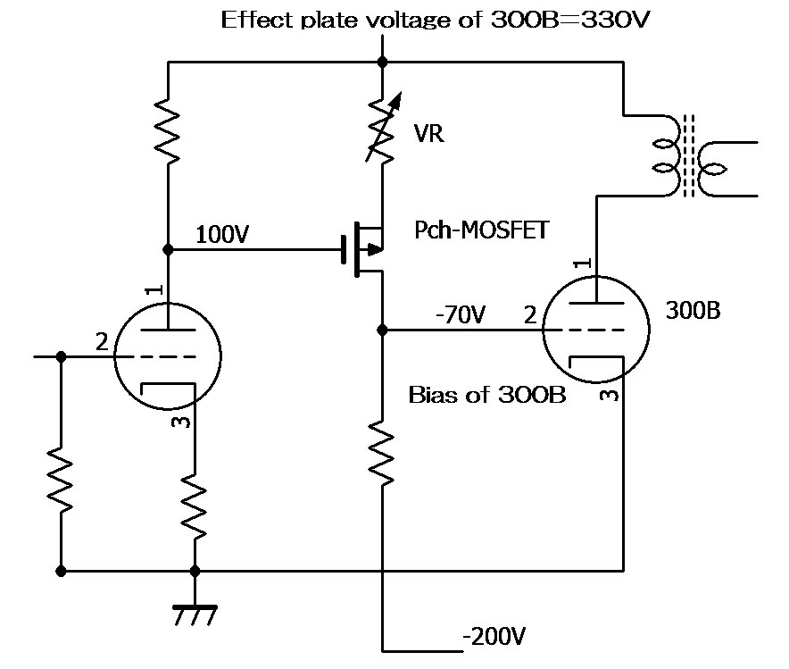
Figure 2
The second stage of Model8 is composed of Pch-MOSFET.
Pch-MOSFET works as a electron tube that operates in a minus power supply.
The drain of Pch-MOSFET that corresponds to the plate of the electron tube
is positioned on the minus power supply side.
Therefore, the power-supply voltage is not piling up on the plus voltage side.
In addition, because the drain voltage becomes a minus side, the drain
voltage can be set to about -70 V by adjusting VR.
Because this minus voltage becomes the voltage of the grid bias of 300B, 300B is made fixed bias operation without the cathode resistor.
As a result, the cathode resistor of 300B is excluded and generation of heat disappears.
To our regret, the circuit of Figure 2 cannot be excellently operated.
The bias voltage of 300B fluctuates by the consumption of the electron
tube, the change of the power-supply voltage and the large voltage gain
of the previous stage.
In addition, the plate current of 300B fluctuates greatly because there
is no cathode resistor in 300B by a few changes of the bias voltage. To
do the stability operation of a long term, a frequent adjustment of VR
is needed.
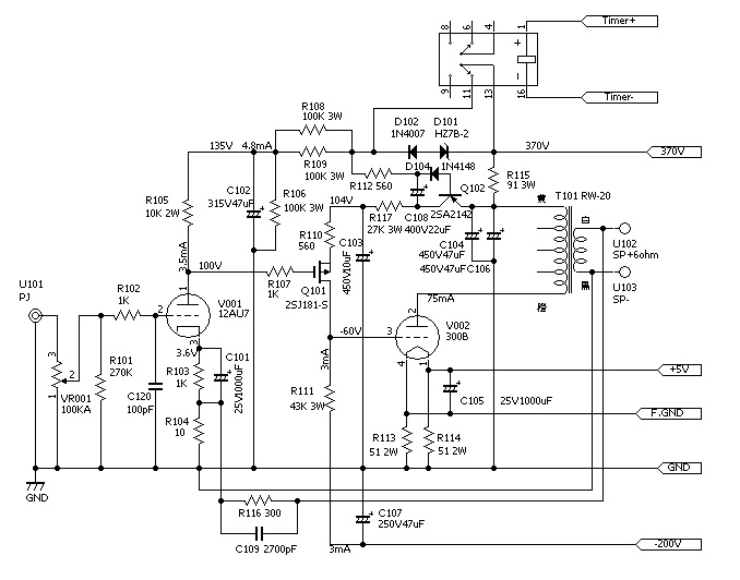
As a countermeasure, we have automated the plate current adjustment.
The circuit of the figure below is not a manual and automatically adjusts
VR in Figure 2.
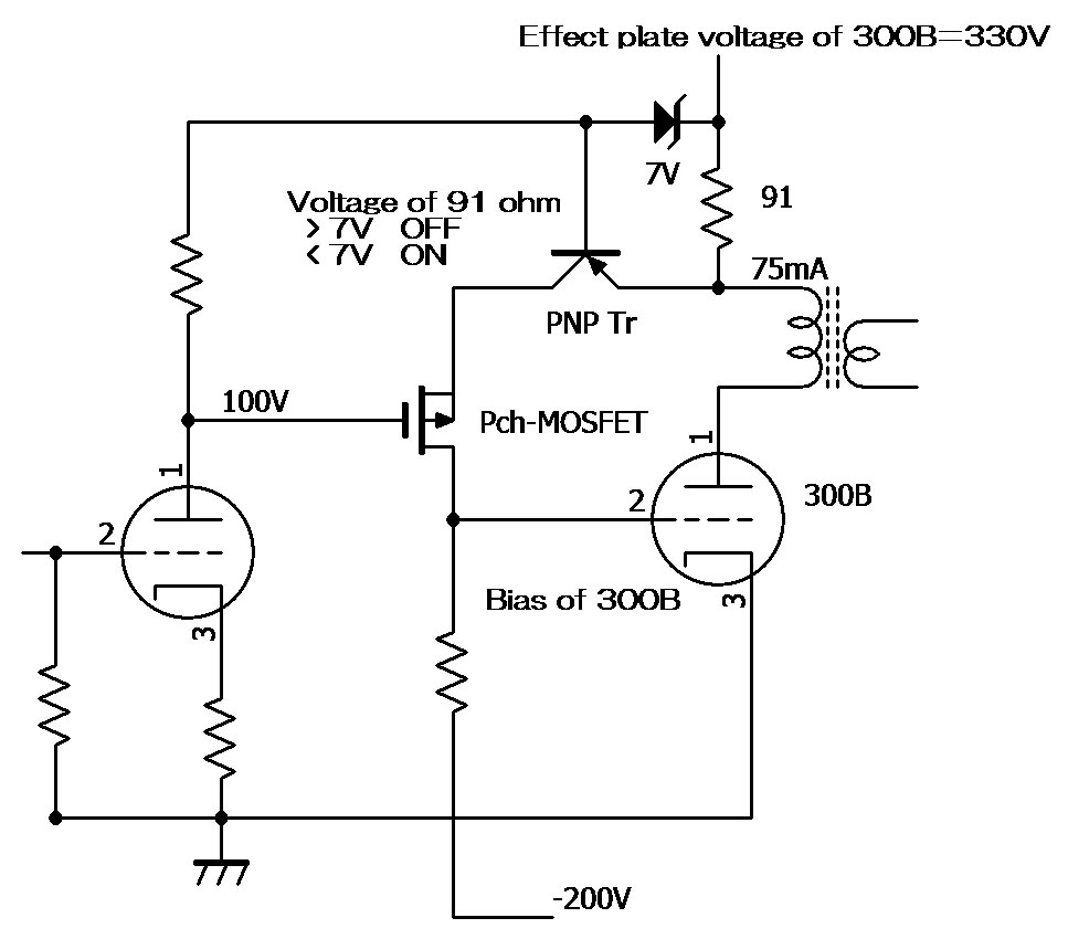
Figure 3
91 ohm between the output transformer and 330V is a resistor for the detection
of the plate current.
This circuit compares the voltage caused in 91 ohm with 7V of the constant
voltage diode by PNP Tr.
PNPTr adjusts the both ends voltage of 91 ohm to 7V automatically.
If the both ends voltage of 91 ohm becomes 7V, the plate current is about
75mA.
When the voltage in both ends of 91 ohm is smaller than 7V (The plate current
is smaller than 75mA), PNP Tr is turned on.
In a word, it is the same as becoming small of the value of VR in Figure
2.
The drain current of Pch-MOSFET increases.
The bias of 300B becomes shallow, and the plate current increases.
Oppositely, when the voltage in both ends of 91 ohm is larger than 7V (The plate current is larger than 75mA), PNP Tr is turned off.
It is the same as growing of the value of VR in Figure 2.
The drain current of Pch-MOSFET decreases.
The bias of 300B becomes deep, and the plate current decreases.
Thus, even if the consumption of the vacuum tube, the temperature change
of the semiconductor, and the change of the power-supply voltage are caused,
the plate current of 300B is kept 75mA.
In addition, 300B can be replaced by no adjustment also in the fixed bias circuit.
To achieve a low noise, the stabilizing direct current is supplied to the filament.
An analog stabilizing supply was used so far.
An analog stabilizing supply generates large heat.
Model8 adopted the latest DC/DC converter for the operation of the filament.
A low noise, space-saving, and low generation of heat were achieved with the DC/DC converter.
The DC/DC converter is a stabilizing supply that used the switching operation.
The DC/DC converter ST1S10 used with Model8 obtains highly effective of
93% by the high frequency switching operation of 900KHz.
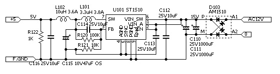
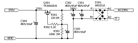
The ripple filter by MOS-FET supplies the ow noise high-voltage .
An efficient R core transformer is used for the output transformer and the power transformer.
The output transformer is RW-20 20W type output transformer.
Enough room to 8W output achieves high sound quality.
![]()
 |
 |
 |
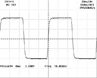
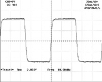
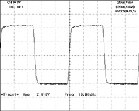
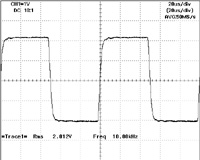
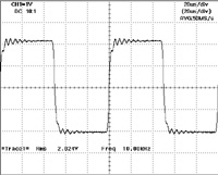
10KHz square wave response
6 ohm load
| 6ohm | 6ohm+0.01uF | 6ohm+0.1uF | 6ohm+1uF |
 |
 |
 |
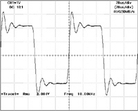 |
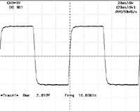
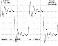
No load
| No load | 0.01uF only | 0.1uF only | 1uF only |
 |
 |
 |
 |