Copyright(C) 2010 Shoichi Yoshimoto
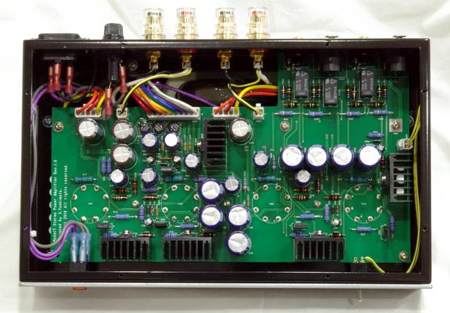
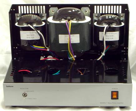
This photograph is only for the explanation. Never open the cabinet because there is a high voltage parts in the inside.
Model7 consists of following parts.
A lot of parts of Model7 are mounted on one print circuit board.
A usual push-pull electron tube amplifier is composed of two or more amplification
stages.
They are the voltage amplification stage, the phase inverting stage, and
the output stage.
Model7 does the high magnification voltage amplification, the phase inverting,
and the output amplification by the single stage.
The single stage amplification achieved a fresh sound quality and a high
stability of negative feedback.
The cascode circuit with MOSFET and the electron tube achieves a high gain and a high withstanding voltage and high power.
The differential amplifier is composed by using this cascode circuit.
The phase inverting can be done by the differential amplification.
Thus, a single stage type push-pull amplifier becomes possible.
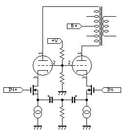
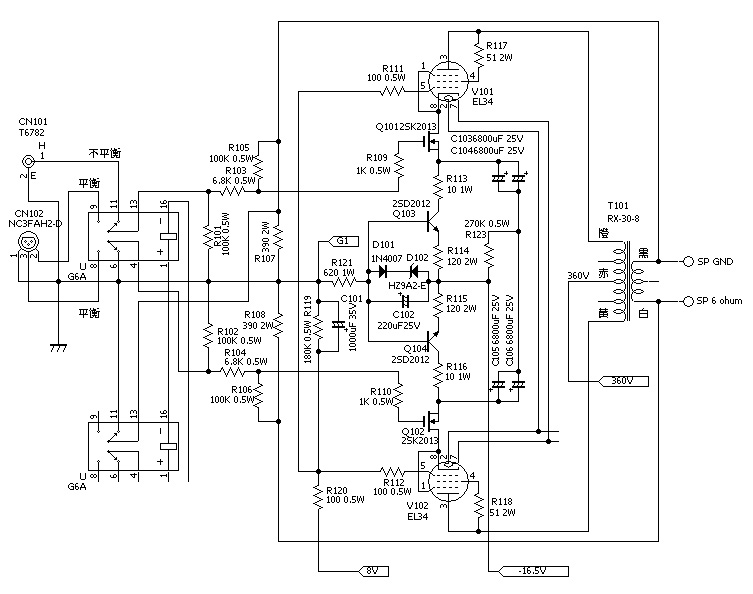
The figure below is a basic circuit configuration.
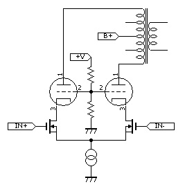
The differential circuit is composed of the current supply, MOSFET, and
the power electron tube.
To obtain appropriate operation, a bias voltage is given to the gate of
MOSFET and the grid of electron tube.
Both sides amplify in the differential motion until the maximum output
because it does the phase inverting.
Therefore, this circuit is class A operation. It is not class AB operation
used with a lot of push-pull amplifiers.
The input signal is given to both IN+ and IN- at the balance
input. The input signal is given only to IN+ input at an unbalanced
input.
This circuit suits a balance input and an unbalanced input.
The gain of this circuit is the following expression.
Gm is a conductance of MOSFET.
Rp is the internal resistance.
Rl is the load impedance of the primary side of the output transformer.
Because the one side of the difference amplifier drives the half of the
load, Rl is 1/2 of the impedance values between P-P of the output transformer.
Gain at plate = Gm * ( Rp // Rl )
// : Parallel value operation
The signal is decompressed with the output transformer and becomes an output
of the amplifier.
Decompression ratio = SQRT( Primary impedance / Secondary impedance of the output transformer )
SQRT : Square route operation
Gain of amplifier = Gain at plate / Decompression ratio
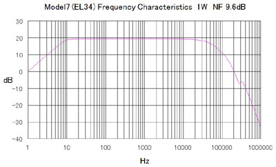
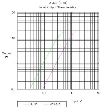
The single stage amplifier of Model7 has about 800 times gain in the plate.
An open gain of Model7 is about 30 times.
Model7 has about 10 times the gain by 9dB negative feedback .
Model7 automatically adjusts the plate current to a constant value.
Because the plate current is adjusted to a constant value, the DC balance
is always kept.
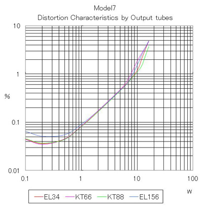
In addition, many kinds of output tubes can be used for Model7 by no adjustment.
The total plate current of the basic circuit is decided with the current
supply.
However, it is necessary to adjust the plate current on both sides to the
same current to keep the DC balance.
In the basic circuit, because the characteristic of MOSFET changes depending
on the current value and the temperature, it is difficult to keep the same
plate current on both sides.
Model7
obtained a steady plate current and an excellent DC balance by using
the Independent current supply differential amplification circuit.
Independent current supply differential amplification circuit
The plate current is decided with the current supply in the Independent
current supply differential amplification circuit.
The bias voltage that adjusts a constant plate current is automatically
given to the electron tube.
The Plate current is kept constant with a electron tube deteriorated and
a different kind of electron tube.
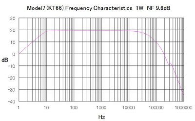
Even if EL34 is used or KT88 is used, the plate current is constant.
Model7 operates with no adjustment when the electron tube is replaced or
a different kind of electron tube is installed.
Balance amplification and unbalanced amplification can be selected with the switch.
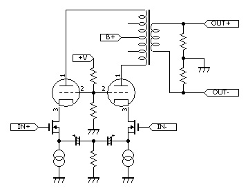
Because Model7 is a differential amplifier, it has a positive phase input and a negative phase input.
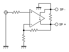
The secondary winding of the output transformer that connects the speaker is a unbalanced type.
However, the positive phase output and the negative phase output can be
made by installing the middle point by resistors as shown in the figure
below.
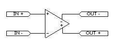
The logic diagram is a figure below.
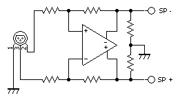
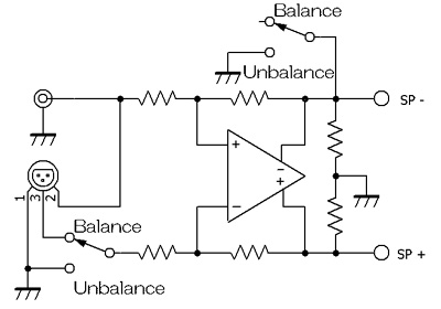
The connecting method of balance amplification and unbalanced amplification is as shown in the figure below.
|
Unbalanced amplification |
Balance amplification |
|
|
|
The circuit with a switch is a figure below. Model7 uses this circuit.
An efficient R core transformer is used for the output transformer and the power transformer.
The output transformer is RX-30-8 30W type output transformer.
Enough room to 16W output achieves high sound quality.
 |
 |
 |
 |
 |
 |