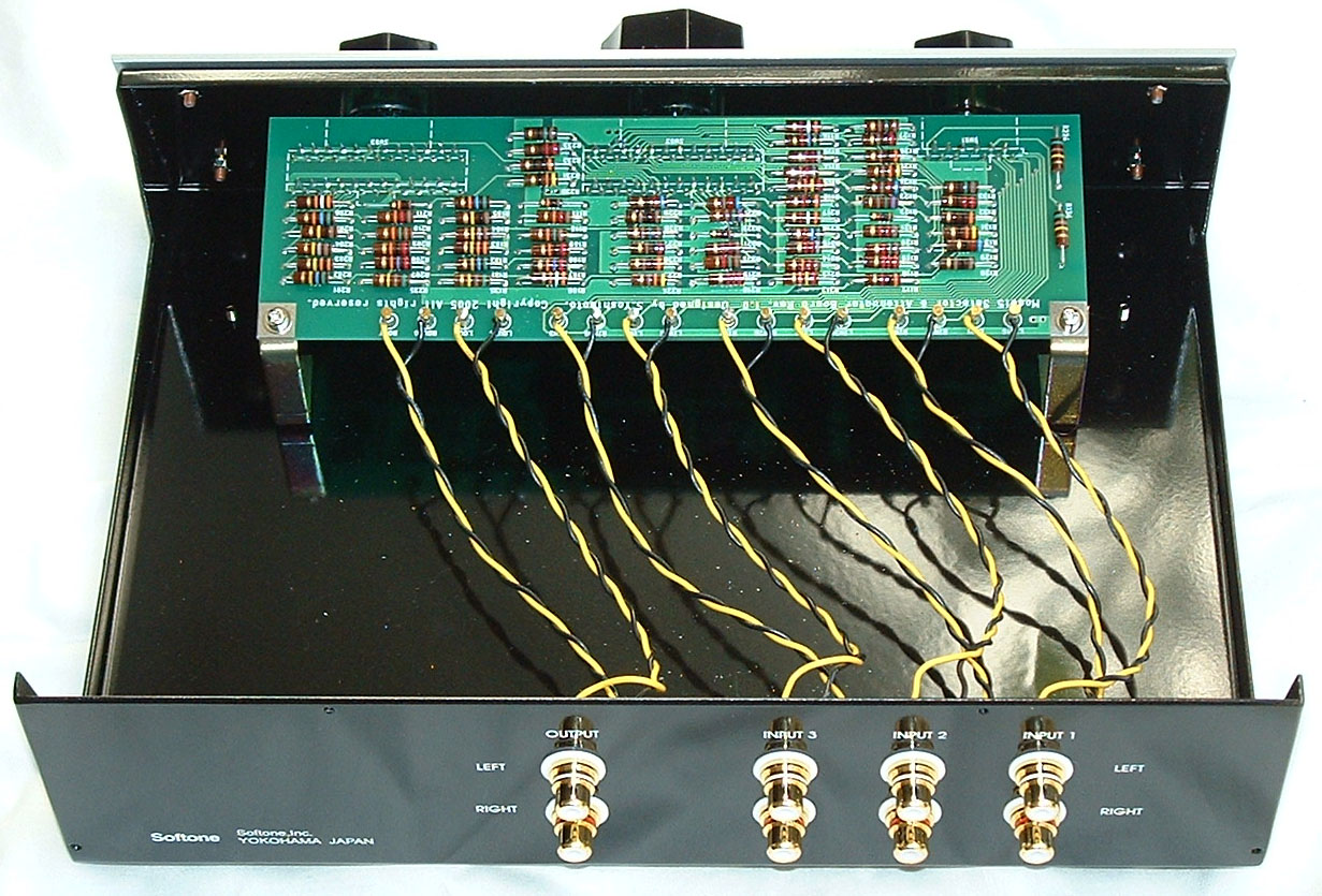
Three rotary switches for input selection, volume control, and balance
control and many resistors are stored in the printed circuit board.
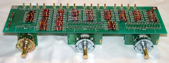
It is a rotary switch for input selection, for volume control, and balance
control to the order from the left.
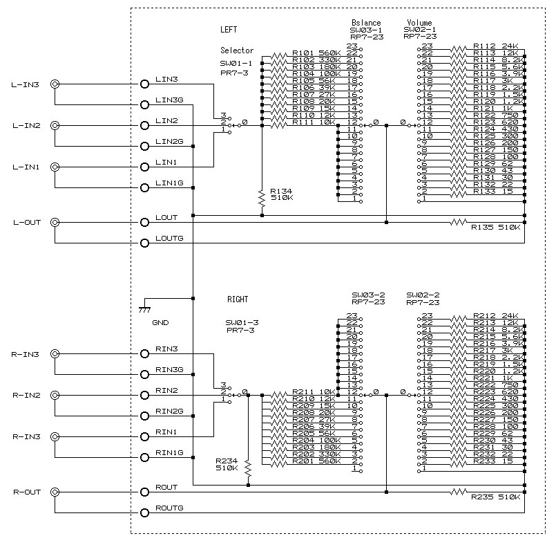
Model5 uses the circuit which a music signal passes only two resistors
in every position of volume and balance control.
The prototype of a circuit is shunt type attenuator of the following figure.
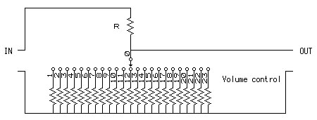
The audio signal inputted from IN is divided by Resistance R and the resistance
selected with a rotary switch.
Since resistance is small towards a No. 1 terminal from the No. 23 terminal
of a rotary switch at order, the volume of the audio signal which appears
in OUT can also be adjusted by becoming small towards a No. 1 terminal
from a No. 23 terminal.
In Model5, balance control is performed by changing upper R resistor further.
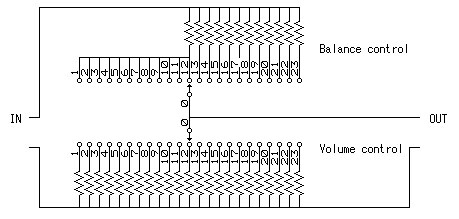
Balance control is performed by switching the upper resistor. Since the
terminal of less than No. 12 is tied mutually, an output is not decreased
even if it switchs to the terminal of less than No. 12. Since the higher
resistor is connected to the terminal of more than No. 12 by order, an
output is decreased, so that it switchs to the terminal of more than No.
12 by order.
Since resistance arrangement of balance control is symmetrical by the channel
on either side, when one channel declines, the channel of another side
is not decreased.
This system can perform volume and balance control only by passing along
two resistors by any positions.
Passage loss and attenuation ratio on each point of volume control are as follows. In order to pass the resistor for balance control, there is 3dB loss in the maximum volume position. Twelve positions of the first half are decreased to 2dB unit, and it decreases to 3dB unit the second half.
| Position | Passage loss dB |
Attenuation ratio dB |
| 23 | 3 | 0 |
| 22 | 5 | 2 |
| 21 | 7 | 4 |
| 20 | 9 | 6 |
| 19 | 11 | 8 |
| 18 | 13 | 10 |
| 17 | 15 | 12 |
| 16 | 17 | 14 |
| 15 | 19 | 16 |
| 14 | 21 | 18 |
| 13 | 23 | 20 |
| 12 | 25 | 22 |
| 11 | 28 | 25 |
| 10 | 31 | 28 |
| 9 | 34 | 31 |
| 8 | 37 | 34 |
| 7 | 40 | 37 |
| 6 | 43 | 40 |
| 5 | 47 | 43 |
| 4 | 50 | 47 |
| 3 | 53 | 50 |
| 2 | 56 | 53 |
| 1 | Infinite | Infinite |
The attenuation ratio from the center position of balance control is as follows. A right-and-left channel is symmetrical in the center position.
| Position | The attenuation ratio from the center position dB |
| 1 | 0 |
| 2 | 0 |
| 3 | 0 |
| 4 | 0 |
| 5 | 0 |
| 6 | 0 |
| 7 | 0 |
| 8 | 0 |
| 9 | 0 |
| 10 | 0 |
| 11 | 0 |
| 12 | 0 |
| 13 | 2 |
| 14 | 5 |
| 15 | 6 |
| 16 | 9 |
| 17 | 12 |
| 18 | 15 |
| 19 | 20 |
| 20 | 25 |
| 21 | 30 |
| 22 | 35 |
| 13 | Infinite |
The input-and-output impedance of Model5 changes with the position of volume
and balance control. Input impedance is 10K ohms the minimum. Output impedance
is 20K ohms at the maximum. It is satisfactory at all to use.
| Input impedance | The volume maximum position : approx. 34K ohms The volume middle position : approx. 11K ohms The volume minimum position : approx. 10K ohms The input impedance of channel which falls volume using balance adjustment goes up to about 200K ohms at the maximum. The input impedance of channel which volume goes up on the contrary does not change. |
| Output impedance | The volume maximum position : approx. 20K ohms The volume middle position : approx. 1K ohms |