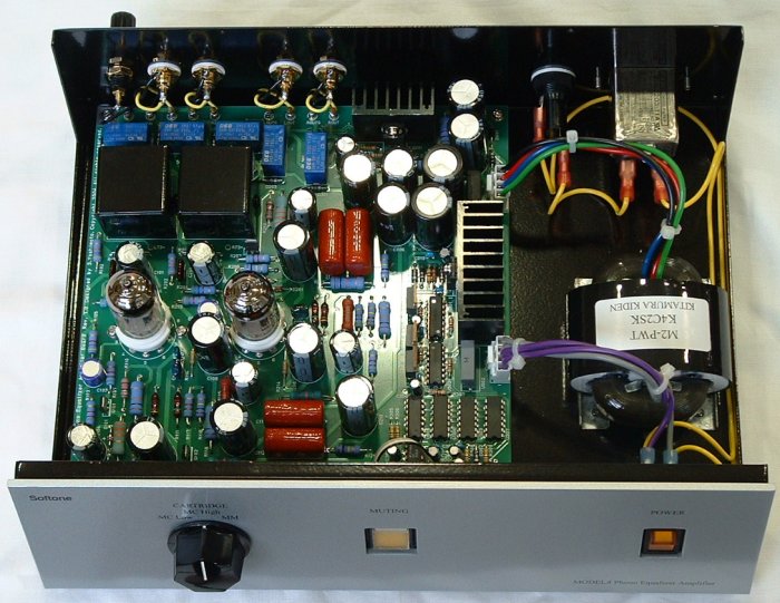
This photograph is only for the explanation. Never open the cabinet because there is a high voltage parts in the inside.
Five blue boxes in the upper left are the relays for cartridge type selection
and muting.
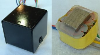
Two black boxes are the MC transformers.
The amplification circuit containing two 12AX7 is arranged in the lower
half of the printed circuit board.
The printed circuit board upper right part is a high-voltage stabilized
power supply for amplification circuits. The central right part is a stabilized
power supply for heater and logic circuits. The lower right part is logic
ICs for relay control.
Model4 consists of following parts.
Almost all parts are mounted in one printed circuit board.
MC transformer is arranged at the nearness of the equalizer amplifier on
the printed circuit board.
By this arrangement, there is no degradation of the sound quality by long
signal transmission.
The MC transformer was newly developed for Model4.
A wide frequency characteristic and high magnetic noise exclusion capability
are acquired by 78% permalloy L type core, and balanced winding structure.
There is 2 sets of 10-ohm winding in a primary of the transformer.
Primary impedance will be set to 40 ohms if 2 sets of winding is connected
in series. When in-series, a voltage ratio is set to 1 to 12, and is suitable
for DENON DL-103 etc.
Primary impedance will be set to 10 ohms if 2 sets of winding is connected
in parallel. When parallel, a voltage ratio is set to 1 to 24, and is suitable
for ortofon SPU etc.
The change of parallel and in-series connection is performed by the relays
arranged near the transformer. Thereby, the shortest signal pass is realized.
![]()
Equalizer amplifier is constituted by two non-feedback amplification units and CR equalizer element placed among them. The non-feedback amplification unit which consists of the voltage amplification stage by 12AX7 vacuum tube and MOS-FET source follower has realized high amplification ratio, and low output impedance and good distortion characteristic.
Feature
Model4 has a control circuit for performing muting and cartridge selection
operation.
If the cartridge type selection is changed, it will once be in a state
to muting, and an output will be intercepted. The muting state is canceled
after changing to the circuit which suited the cartridge type. A cartridge
type can be changed with non-noise. And there is also no generating of
the loud noise by unprepared change of a cartridge type.
The control circuit consists of standard logic ICs. Although it is a circuit where a one-chip microcomputer is usually used, it dislikes that a high-speed CPU clock exists in the equalizer amplifier handling a low level signal, and the control circuit consists of a standard logic IC and a super-low-speed clock (1Hz).
Model4 has 300V power supply for equalizer amplifier circuits, 6.3V power supply for heater of 12AX7, and 5V power supply for control circuits. Any power supply is stabilized.
High quality parts are used for Model4.
Low noise vacuum tube. Glass epoxy circuit board. Large-sized resistor.
Large-sized film capacitor. High precision capacitor. Quality tube socket.
Gold plated RCA jacks.
![]() Amplification ratio
Amplification ratio
| Cartridge type | Amplification ratio at 1KHz | |
| MM | 180 | 45dB |
| MC Low | 2200 | 69dB |
| MC High | 4300 | 72dB |
![]() RIAA characteristic
RIAA characteristic
![]() Distortion characteristic
Distortion characteristic
![]() Noise, S/N characteristic
Noise, S/N characteristic
| Cartridge type | Noise | |||
| No Compensation | IEC Compensation | |||
| MM | 0.6mV | -64dBV | 0.14mV | -77dBV |
| MC High | 0.9mV | -61dBV | 0.22mV | -73dBV |
| MC Low | 1.0mV | -60dBV | 0.23mV | -73dBV |
| Cartridge type | Noise ratio in Input | |
| No Compensation | IEC Compensation | |
| MM | -109dBV | -122dBV |
| MC High | -127dBV | -139dBV |
| MC Low | -132dBV | -145dBV |
| Cartridge type | Input level | S/N | |
| No Compensation | IEC Compensation | ||
| MM | 5mV -46dBV | 63dB | 76dB |
| MC High | 0.5mV -66dBV | 61dB | 73dB |
| MC Low | 0.2mV -74dBV | 58dB | 71dB |